


Lilly Electronics
Mini USB 1602 LCD 5V LC100-A Precise electronic Inductance Capacitance meter
Mini USB 1602 LCD 5V LC100-A Precise electronic Inductance Capacitance meter
Couldn't load pickup availability
LC100-A basic technical indicators:
Capacitance Accuracy: 1pF-1uF 1%
1uF-10uF 5%
Minimum resolution(C Range): 0.01pF
Inductance Accuracy: 1uH-100mH 1%
Minimum resolution(L Range): 0.001uH
Large Inductance Accuracy: 100mH-1H 1%
1H-100H 5%
Minimum resolution(Hi. L Range): 0.001mH
Large capacitance Accuracy: 1uF-100mF 5%
Test Frequency: capacitance, inductance profile about 500kHz; the large inductance of about 500Hz-50KHz.
Effective display digits: 4 digits
Display: LCD 1602
Powered by: mini USB interface to take power or 5V power supply
LC100-A Function table:
| Hi.C | Hi.L | L/C | Corresponding function |
| 0 | 0 | 0 | Capacitance(C Range) |
| 0 | 0 | 1 | Inductance(L Range) |
| 0 | 1 | 1 | Large Inductance (Hi.L Range) |
| 1 | X | X | Large Inductance (Hi.C Range) |
| 0 | 1 | 0 | Gears error, fix |
Interface: Mini USB & 5.5DC Socket (inner: positive pole, outer: negative pole)
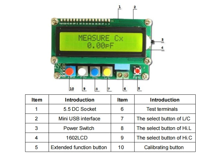
Direction for use
(1).Switch on the L/C Meter
(2).Chose the corresponding files, inductance: Lx, capacitance: Cx, big inductance: HL, big capacitance: HC. Display as follows (testing terminal open loop) :
Capacitance(C) show:MEASURE Cx 0.00pF
Inductance(L) show:MEASURE Lx OVER RANGE
Inductance(Hi.L) show:MEASURE Hi.L OVER RANGE
Large capacitance(Hi.C) show:MEASURE Hi.C 0.00uF
Display as follows( testing terminal short circuit):
Capacitance(C) show:MEASURE Cx OVER RANGE
Inductance(L) show:MEASURE Lx 0.000uH
Inductance(Hi.L) show:MEASURE Hi.L 0.000mH
Large capacitance(Hi.C) show:MEASURE Hi.C 0.00uF
(3).When testing terminal open loop the measured value of capacitance is not “0”, or witch of the inductance is not “0” as the testing terminal short circuit, you can reset to “0” by ways of capacitance model and inductance model, as follows:
(a) Capacitance model
Press red button as testing terminal open loop, it displays “CALCULATING…”, keep pressing for one second, when “CALCULATING…OK” displayed, resetting to “0” is finished, and “0.00pF” is displayed, then capacitances can be measured.
(b) Inductance model
Press red button as testing terminal shirt circuit, it displays “0.000uH” or “0.000mH”, and then inductances can be measured.
(4). Please press black function button as results displayed, and corresponding frequency will be displayed.
Note:
1. Please reset to “0” before testing a capacitance or an inductance, or errors may be appeared. Even if “0” displayed before measuring, resetting to “0” is needed.
2. At the time of resetting to “0”, when“CALCULATING…OK” appeared, please keep pressing for 2 to 3 seconds, and the parameter written to “<DATA SAVED>” will be prompted, then release.
3. Resetting to “0” is forbidden as components are being measured. If you do it, please shut down immediately and restart, then reset to “0”.
4. The time of measuring a big capacitance (above 10mF) may be more than one second, and it needs seven to eight seconds to get the measured value of the capacitance (100mF).
5. Forbid to measure a capacitance which is not discharged, otherwise it may damage the mainframe.
Share


Tested in an audio setup and it performs reliably. No issues noticed during use.