


lilly electronics
Three Phase Sinusoidal Generator Phase Adjustable 0-360 Degrees 0.1-2000Hz
Three Phase Sinusoidal Generator Phase Adjustable 0-360 Degrees 0.1-2000Hz
Couldn't load pickup availability
Three Phase Sinusoidal Generator Phase Adjustable 0-360 Degrees 0.1-2000Hz
Specifications
Third, the technical parameter table:
1 Output frequency range: 0.1 ~ 2000Hz
2 output frequency resolution: 0.1HZ
3-phase displacement phase range: 0 ~ 360 degrees
4 phase shift phase resolution: 1 degree
5 signal amplitude: 1 to 5VDC (maximum amplitude 5.0Vpp)
6 Working voltage: 7 ~ 12VDC
7 Working current: <50mA
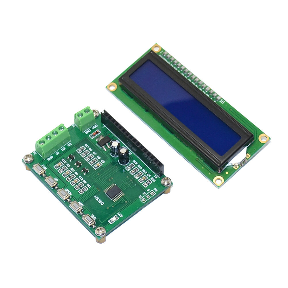
8 size: 56 * 45 * 20mm (length X width X height)
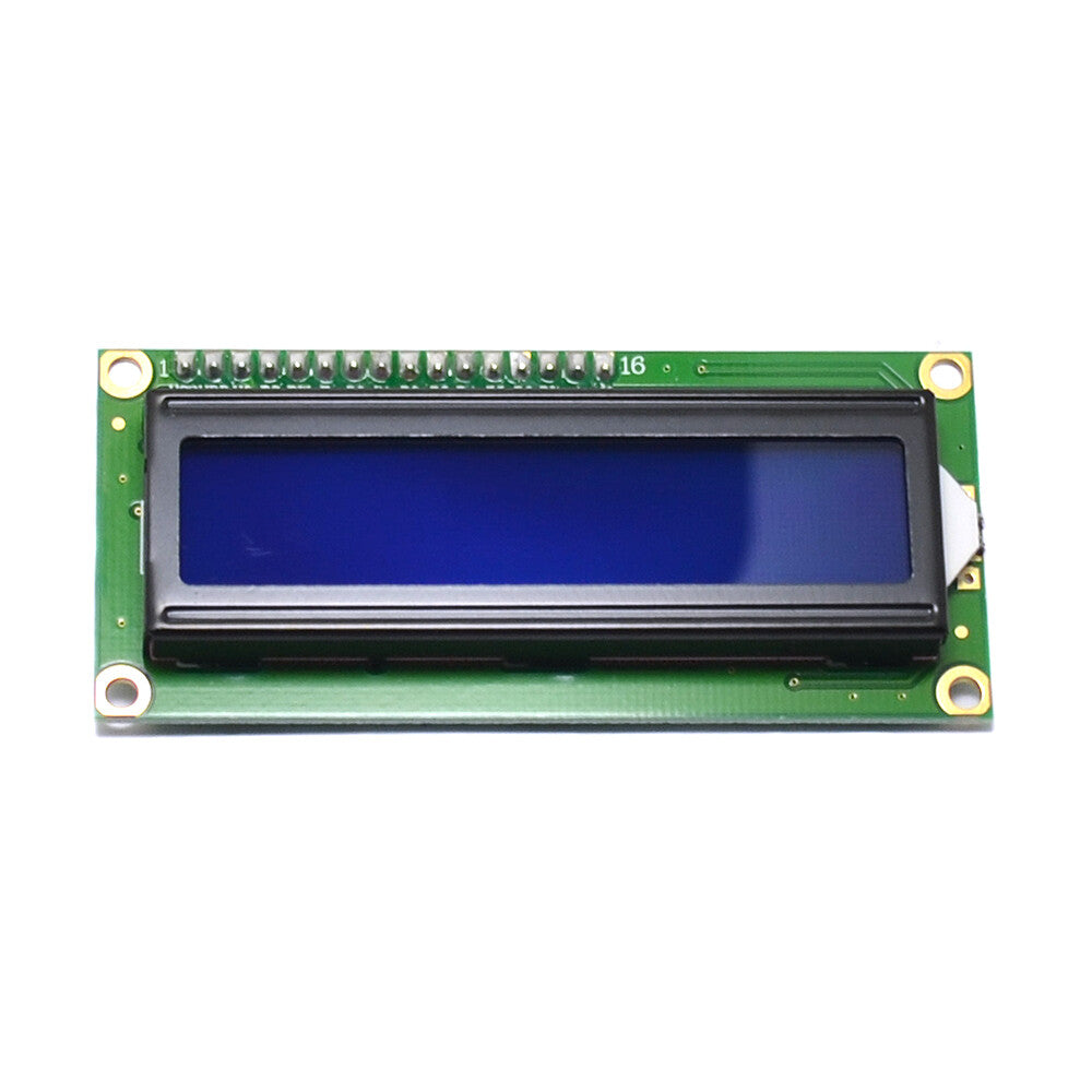
Interface display and operation instructions:
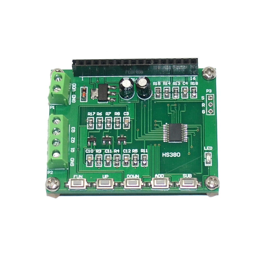
(1) Button description:
FUN: Function key; UP: Set the interface down; DOWN: Set the interface up; ADD: Add button; SUB: Decrease button;
4.1 Setting the output frequency
?Interface display font:
First line "1. Frequency"
The second line "* 1 100.0Hz"
Key operation:
FUN: (Select the operation bit of the setting data) (Press and hold the FUN key to save the set parameter value)
ADD: auto-add key;
SUB: Decrement key;
4.2 、 Control three-phase output voltage
Interface display font:
First line "2.Output Voltage"
The second line "60n"
Key operation:
Set the measurement frequency range key: (LEFT: auto-add key)
4.3. Set the phase difference between phase A and phase B (phase A is the reference point)
Interface display font:
The first line "3.A-> B Phase"
The second line "120C’ "
Key operation:
ADD: auto-add key;
SUB: Decrement key;
4.4. Set the phase difference between phase A and phase C signals (phase A is the reference point)
Interface display font:
The first line "4.A-> C Phase"
The second line "* 1 240C’ "
Key operation:
ADD: auto-add key;
SUB: Decrement key;
4.5. Set start / stop output filtering
Interface display font:
The first line "5. Filter SET"
The second line "Filter = ON"
Key operation:
ADD: start / stop;
Notes: (1) Startup: Connect the filter capacitor to the output to output a sine wave signal.
(2) Stop: No filter capacitor is connected to the output, and PWM signal is output.
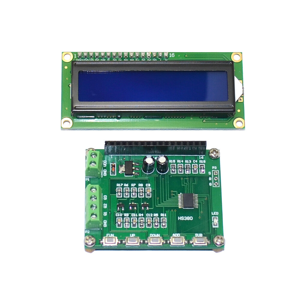
Five, wiring
P1 wiring definition:
Number symbol meaning
1VDD module power positive (7V ~ 12V)
2 GND Module Power Negative
P2 wiring definition:
Number symbol meaning
1Q3C phase signal output
2Q2B phase signal output
3Q1A phase signal output
Package: 1 * three-phase sinusoidal signal generator
Share
Tested after installation and everything functions as expected.